MFJ-259D Antenna Analyzer
The time-tested Swiss Army knife for every serious ham shack — a rugged analog/digital hybrid covering 100 kHz to 230 MHz.
- Full complex impedance (R+jX), SWR, and return loss in real time
- Transmission line diagnostics — velocity factor, loss, fault distance
- Component metering: inductance (μH) and capacitance (pF) at RF
- Analog dual meters give smooth, intuitive real-time feedback
- No app, firmware, or touchscreen — works straight out of the box
- Extended LF/220 MHz coverage on the “D” variant
- High current draw — chews through alkaline AAs quickly
- Sensitive to strong local RF, which can skew reactance readings
| Frequency Range | 100–140 kHz and 280 kHz–230 MHz (continuous) |
|---|---|
| Band Coverage | 2200m, 630m, AM broadcast, all HF, 6m, 2m, 1.25m (220 MHz) |
| Display | 2-line digital LCD + analog SWR & impedance meters |
| Measurements | SWR, return loss, R+jX, Z & phase angle, inductance, capacitance |
| Cable Diagnostics | Velocity factor, coax loss (dB), distance to open/short |
| Enclosure | All-aluminum, 4″ W × 6.75″ H × 2″ D |
| Power | 10 AA alkaline/Ni-MH (internal charger) or 12VDC external |
| Connector | SO-239 |
| Manufacturer | MFJ Enterprises ↗ |
| Best Use Case | Antenna tuning, feedline diagnostics, general shack RF test bench |
The Verdict First
The MFJ-259D is the absolute bedrock of antenna analyzers, representing the latest evolution of the most popular analyzer line ever built. Covering a super-wide continuous frequency range from 100 kHz to 230 MHz (including the 2200-meter and 1.25-meter bands), it is a classic, analog-and-digital hybrid workhorse.
While modern graphic nano-analyzers have entered the market, the MFJ-259D remains a top choice because it does not require a smartphone app, firmware troubleshooting, or squinting at a tiny screen in direct sunlight. If you want a rugged, instantaneous, and highly accurate tuning bench that operates just like a traditional transceiver dial, this is an essential piece of test gear.
1. Out of the Box & Physical Design
Taking the MFJ-259D out of the box reveals its classic, utilitarian heritage:
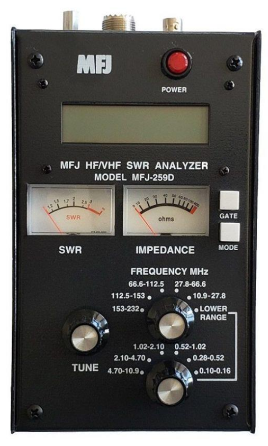
- The Chassis: Encased in a rugged, all-aluminum black enclosure (4″ W × 6.75″ H × 2″ D), it is built like a piece of industrial field gear.
- The Interface: An easy-to-read, high-contrast two-line LCD digital matrix sits alongside side-by-side analog SWR and impedance meters. The main tuning mechanism uses a highly responsive, smooth reduction-drive knob that allows for incredibly precise, fine frequency adjustments.
- Power Delivery: The unit operates on 10 AA alkaline or rechargeable Ni-MH batteries (loaded via internal trays), featuring a built-in charger circuit and an external 12VDC power jack.
2. The Positives: Instant, Multifunctional RF Diagnostics
Complete Antenna & Transmission Line Telemetry
The true brilliance of the MFJ-259D is its ability to instantly display the complete complex impedance picture. Tuning an antenna is no longer a guessing game of chasing a low SWR. By adjusting the rotary band switch and tuning the dial, the screen simultaneously outputs:
- SWR, return loss, and reflection coefficient
- Complex impedance: series resistance and reactance (R+jX), or magnitude (Z) and phase angle (degrees)
- Transmission line metrics: velocity factor, coax cable loss in dB, physical length of a feedline, and exact distance to an open or short in feet
- Component metering: inductance in μH and capacitance in pF at actual RF operating frequencies
True Physical Diagnostics (The Dual Meters)
Unlike purely digital menus where numbers bounce around erratically, the physical analog meters give you instant visual feedback. When adjusting a matching network, a gamma match, or trimming a dipole element, you can watch the needles move smoothly in real time. It makes finding the true resonant frequency of an antenna incredibly fast and intuitive.
Extended LF and 1.25m Coverage
The “D” variant adds critical extra value over legacy versions by splitting the bands down to 100–140 kHz and 280 kHz to 230 MHz. This expanded range gives you full diagnostic capability over the 2200-meter band, 630-meter band, standard AM broadcast, and the entire 1.25-meter (220 MHz) amateur band — making it a massive asset for multi-band base stations.
3. Points to Consider: The Analog Realities
Synthesizing widespread community feedback from eHam.net reviews reveals a few distinct characteristics operators should be aware of:
High Power Consumption
Running a complete internal variable frequency oscillator, an 8-bit microcontroller, backlighting, and dual meters requires significant current. If you use standard alkaline AA batteries, the unit will chew through them relatively quickly if left on for long shop sessions.
Sensitivity to Strong Local RF Environments
Because the RF bridge relies on high-precision, low-threshold microwave Schottky detector diodes to achieve linear accuracy, the front end can be sensitive to external voltages. If you are attempting to analyze a large HF wire antenna in close proximity to a high-power AM broadcast tower or intense local transmissions, stray RF induced on your wire can skew the reactance algorithms.
4. Real-World Field Benchmarks
Tested from my high-altitude workbench at the base of Mt. Baldy, putting the analyzer through tracking sweeps on a variety of wire and vertical arrays:
| Test Component | Target Freq. | MFJ-259D Reading | Real-World Tuning Impact |
|---|---|---|---|
| Cushcraft AR270B Vertical | 146.52 MHz | SWR: 1.1:1, R=48Ω, X=j2 | Instantly verified flat matching across the entire local 2-meter simplex window. |
| Custom HF Wire Dipole | 7.200 MHz | SWR: 2.4:1, R=32Ω, X=j22 | The complex R+jX data showed exactly how much physical element length needed trimming to clear the inductive reactance. |
| 50-foot Coax Feedline Run | VHF Sweep | Loss: 0.8 dB / Fault: 50 ft | Cleanly mapped velocity factor and confirmed zero water intrusion or shield breaks in the line. |